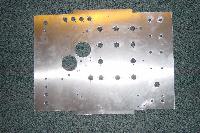
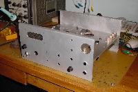
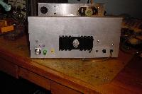
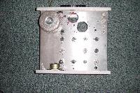
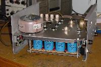
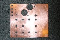
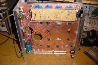
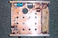
Well, if it ever gets completed "TR40" is an all tube SSB transceiver covering the 40M band 7.0-7.1 MHz. I started this project about 2 years ago when I got a toroidal transformer wound to my specifications with this design in mind. Until Easter 2002 that's as far as the project progressed, apart from talking about it :)
Most of my friends and colleagues think it won't get finished, and based on past experience I'm inclined to agree with them! Despite this, I'm giving it my best efforts and hope to get onto the interesting stuff before the initial wave of enthusiasm fades.
Mains wiring complete and transformer connected. PSU section completed producing 12.6 (regulated), -140, +140, +300 and +900 volts (eeek!). The 12AX7 microphone amp is now working.
Next job: TX audio cathode follower, xtal BFO/CIO and diode balanced modulator.
The design has a single IF frequency of 4.43 MHz and uses a 2.57-2.67 MHz VFO to heterodyne to / from the 40 M band. I've 12 signal tubes in the design (eleven 9 pin and one 7 pin) together with four 7 pin VR tubes and two 807s which have their own unusual 5 pin base.
I recently bought ten NOS RCA 807s for £20 (about $30) - no boxes though. Apart from being rather tall (as compared with 6146, 6JB6, 6JS6 etc.) they'll make a great set of finals for this radio. To make the unit have the lowest overall height I decided to mount the bases for these well below the chassis.
The (initial) valve line up is: 12AX7 mic amp, 6C4 cathode follower, 12AT7 BFO/CIO & cathode follower, 6BY7/EF85 IF amp (tx & rx), 6BY7/EF85 2nd rx IF amp, 12AT7 balanced tx mixer, 6BX6/EF80 driver, two 807 in PA. The rx mixer is a 12AT7 (in a "Pullen" configuration), IF amps as noted, 12AT7 product detector, 12AX7 AF preamp & AGC amp, 6AB8/ECL80 AF o/p. The VFO uses a 12AU7, the 2nd section as a cathode follower.
I'm hoping if I can't get the various stages working as I envisage, I've enough valves to perhaps be able to change types and circuit configurations. There are many double triode circuit configurations for the two mixers and product detector used in the design. The tx balanced modulator will use small signal semi-conductor diodes (hey, it was good enough for the T-4XC :)
By using the 9 pin EF80 and EF85 pentodes I buy a little extra flexibility as there are at least 2 other members in the EF80/85/183/184 family (that's 6BX6/6BY7/6EH7/6EJ7) which, although sharing an identical pin-out, have very different characteristics.
All valves (except the 807s) have 6.3V 0.3A heaters (and/or 12.6V 0.15A for the double triodes) and so by employing a series-parallel configuration can be arranged to use a 12.6V heater supply. The 6.3V 0.9A 807 filaments are connected in series.
To keep mains hum out of the design DC is used for the heater rail. To help keep the VFO stable this 12.6 V rail is regulated and also "slow started" to prolong the life of the valves used. This 12.6V rail also powers the various relays used for T/R switching etc.
Click on any of the pictures to see a larger version of them.