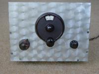
I recently bought a small 1920's style radio at a vintage radio rally. I'd always thought items of this age were likely to be very expensive but this one cost me £20 (about $30), not unreasonable I thought.
The unit is certainly no work of art but does use vintage components. It is of course possible that the unit was assembled more recently than its components suggest but the level of grime on the coils indicate that they were certainly wound a long time ago. Some of the soldering was recent; I'm not sure if the last owner thought that it worked well or not but it appears he/she made good some of the connections.
The unit is a single valve regenerative short wave receiver covering very roughly 5 to 15 MHz. In total, 1 fixed and 3 variable capacitors are used together with 1 resistor, 1 switch, two coils (on the same former) and of course the triode valve. The antenna is connected via a series variable capacitor and crocodile clip which taps into the tuned circuit.
The valve is a "VR21" which is a directly heated triode with a 2 volt filament. The early radios used a single lead acid accumulator cell to power the filament(s), the High Tension being provided by large dry cells. Periodically the owner would take the exhausted accumulator to a local garage which had facilities for recharging it. The dry cells would last longer as the current consumption from the HT line was generally quite low.
Later, by perhaps the early or mid 1930's, domestic electrical supply became more commonplace and radios evolved into much larger and more sophisticated units that were powered from the mains supply. Generally, these mains powered radios were of the super-heterodyne type, rather than the regenerative and "tuned radio frequency" types that typified the early battery operated valve radio sets.
To date I've verified the unit is basically working and made some sensitivity measurements using a signal generator. I did not have a 2 volt power supply and rather than use a resistor from and a higher voltage supply I decided to try a 1.5 volt 'D' size dry cell. This only makes the filament glow a dull red, just visible in a darkened room, but never the less the unit would operate with this heater voltage.
The rheostat visible in some pictures is a 350 Ohm unit and although it appears to be connected is itself open circuit as connected end to end and so has no effect. One end to the wiper contact still works and I'm working out how to incorporate this into the circuit - if at all. I've seen rheostats in filament circuits but I think this particular one has too high a resistance for this application.
I used a 50 volt DC power supply to provide the HT and measured currents of around 1 mA at this voltage. The unit would regenerate at 7 MHz but as I decreased the frequency the unit dropped out of regeneration, even with the control set to the maximum.
I'd rather not start increasing the feedback winding and so I will try a higher voltage as well as a 2 volt heater voltage to try to establish the lower frequency limit of the set. I'm interested in CW (Morse) and Single Side Band reception on the Amateur radio bands and the reception of these modes requires the set to be oscillating both in order to demodulate the incoming signal and also to provide a very high gain from the otherwise low gain valve.
If I can fix the regeneration maybe I will add a fixed capacitor in parallel with the tuning capacitor (if required) to bring the unit down to work on the 3.5 MHz band as well as the 7MHz band.
No audio output transformer is present and so I simply connected a pair of old high impedance headphones in series with the anode circuit. Using these headphones I was able to obtain the following results for receiver sensitivity:
HT voltage:   50 V (would be better with 100 volts I think)
HT current:   1 mA
LT voltage:   1.5 V (should be 2 V)
LT current:   85 mA (would be 100 mA at 2V)
Frequency:    7000 kHz
Mode:         CW
o/p:          Genuine 1920's headphones, in series with HT and anode RFC.

(Minimum Discernable signal)
MDS:          -90 dBm or roughly S7 based on S9 = 50 uV and 6 dB per S point.
Min usable:   about -80 dBm or pretty nearly S9.

For reference -90 dBm is 1 pico watt or about 14 uV RMS into 50 Ohms.
I think that with greater voltage and more tweaking I could see better than a -100 dBm MDS*. I'm also a little deaf and so someone with normal ears could probably do better again. I did try using an audio transformer and sensitive (but low impedance) modern headphones but they were not as good as the old 'phones although they were a lot more comfortable!
It requires a steady hand to operate the set and the contacts on the main variable capacitor are dirty and so the tuning is somewhat erratic at present. I think it will need a good few hours of usage to determine whether or not the set is viable for a two way contact (together with a companion transmitter). I'd like it to be so but it's really a simple broadcast set.
* To put these figures in context my twin double-triode regenerative 80m receiver has an MDS of better than -110 dBm when driving a loud speaker but this set does employ 4 triodes rather than 1.